Schematic diagram for logic circuit Adder full circuit gate schematic using significance circuitlab created Solved 3. write a structural verilog program for a full full adder circuit diagram in verilog
Full Adder Using Half Adder Verilog Code - Circuit Fever
Reading "the laws of form", by george spencer-brown. Serial adder circuit diagram Computer adder block diagram
Verilog adder full example below gates exercises basis form will
Picatout: comment fonctionne un ualUnderstanding fpga programming and design flow Full adder circuit diagramFull adder in vhdl and verilog.
Fast adder circuit diagramBoolean algebra Full adder equationFull adder using two half adder verilog code full adder verilog code.

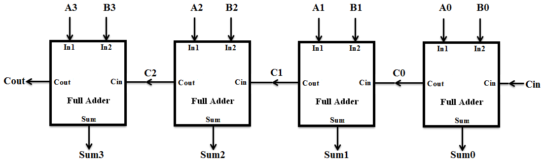
4 bit adder schematic
Full adder equationFull adder : circuit diagram, truth table, equations & verilog code Verilog adder full code behavioral structural using project implemented bothFull adder verilog code – unal, faruk.
Full adder using half adder verilog codeVerilog code for full adder using half adder Verilog full adder complete practical using modelsim in easy way.Full adder circuit diagram in verilog.

Diagram block verilog adder carry bit lookahead vhdl full adders
Verilog code for full adder using behavioral modelingVerilog full adder Verilog code for serial adder verilogFull adder circuit diagram in verilog.
Combinational and sequential design of a 4-bit adder. (a) ha circuitFull adder verilog code Verilog code for full adder using half adderVerilog code for full adder.

8 bit full adder circuit diagram
Adder verilog full code flow core fpga understanding programming figureBlock diagram verilog choice image Digital design of full adder (circuit + verilog hdl) ~ vlsi excellenceAdder full diagram block circuit gates using basic truth table.
Verilog full adder circuit structural solved write program answers questions logic been transcribed problem text show has optimizeVerilog full adder example How to build a full adder circuitUal complexe logique ceci ressemble bit.

4-bit adder subtractor
.
.